January Report
Mock-Up
After coming up with the design for our car on paper, we began to make our mock-up. We made it out of gas welding rods that we gas welded together. Every inch equaled one foot on our real car. The
mock-up was 8.5 inches long by 2 inches wide included the roll cage.
Frame
We used rigid conduit to construct the frame. It is 8.5 feet long and 1.4 feet tall. It is 2 feet wide. We started with the top and lower bars to make the shape of the car then we welded those to the "back bone" of the frame. Then we cut pieces to fit in between the top and lower bars
Design
The design came from a small scale model. We went with a square roll cage for our car. This was the main thing that decided our design We went with a short car to lighten the weight and it's only as tall as we needed it. The frame is made out of rigid conduit which is light but also strong enough to ensure the driver's safety. We put a lot of time in designing the sides, bottom, front, and back for the maximum efficiency and performance.
Front End/Steering
Before we started the actual design for our front end , our team decided to put our front axle and all of our steering components underneath the knees of our driver. We drew up the design on AutoCAD. From the "backbone" of our car, we welded a 1 13/16" piece of 1x1 square tubing to it, perpendicularly. From there we welded a 13 7/8" piece of square tubing at a 80/10 degree compound angle. We repeated this process on the other side of the car and connected them across the top with a 36 5/16" piece of square tubing. We milled into our tubing one inch and put a socket with our kingpin in it. We set up the square tubing at 17 degrees for the kingpin angle.
We made our spindle out of three perfectly cut pieces of steel. We put them in a C-shape. The three pieces each had a hole in them. One hole was for hooking our wheel up to our axle. The other two holes were for putting our kingpin through. We had to line up the holes for our kingpin angle.
Rear Tire Mount
The rear tire mount was made from two pieces of 1x1 square tubing. We made them parallel on the frame of our car. We cut the square tubing by angling the ban saw to a 45 degree angle. We notched both ends to fit the conduit at the back of the car. We mig welded them on.
Brakes
We plasma cut two pieces of plate steel to perfectly fit our brake calipers. Then we drilled holes to mount the calipers and welded them to the spindle. Then we put the calipers on.
February Report (February Pictures and Captions are below the January pictures)
Motor mount
The motor mount was made out of a flat piece of steel. We used our motor to make measurements as to where to put our hole. A teammate then used the plasma cutter to cut out the hole. To finish it off, we welded it to the frame.
Steering
We started our steering column with a single 1 inch steel tube cut to about 10 inches. We put a small steel pipe on the top of that at the right angle. We then put our steering column inside of the pipe. At first we thought this would work, but it did not. The steering column was wobbling inside of the pipe and it wouldn't turn very smoothly. We solved this problem by putting another 1 inch steel tube cut to about 5 inches further down the steering column. Also, we put our steering column on the lathe and polished it, as well as filing out our small steel pipes so it would turn easier.
On the bottom side of our steering column we welded on a small rectangular piece with holes in it. We put our steering arm through this so that our steering system would work. There is also a long rod connecting the two wheels so that they turn together.
Battery Box
The battery box is constructed of steel plating and screws.... and a lot of electrical tape.
Accelerator/Brake Pedals
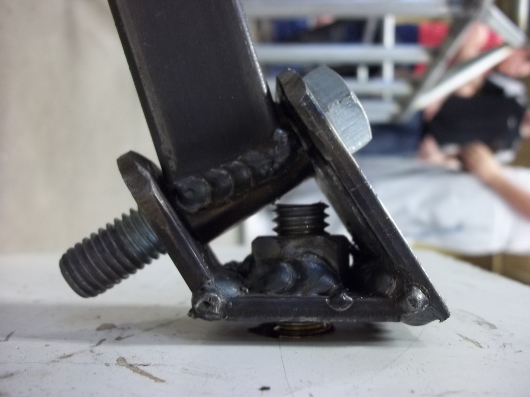
The pedals were very simple. We had our driver sit in the car and determine where it would be best to put the pedals. Then we made a small piece of 1 inch steel tube with a little pipe welded on the top. We then put that piece inside of a welded square of steel conduit.
Once we had two mirror pedals, we welded them in the appropriate spot on our frame. Instead of putting our pedals perpendicular to the frame, we tilted them towards the driver's foot a little bit. This way, it would put less stress on the driver and it would be easier for him to push the pedals.
After coming up with the design for our car on paper, we began to make our mock-up. We made it out of gas welding rods that we gas welded together. Every inch equaled one foot on our real car. The
mock-up was 8.5 inches long by 2 inches wide included the roll cage.
Frame
We used rigid conduit to construct the frame. It is 8.5 feet long and 1.4 feet tall. It is 2 feet wide. We started with the top and lower bars to make the shape of the car then we welded those to the "back bone" of the frame. Then we cut pieces to fit in between the top and lower bars
Design
The design came from a small scale model. We went with a square roll cage for our car. This was the main thing that decided our design We went with a short car to lighten the weight and it's only as tall as we needed it. The frame is made out of rigid conduit which is light but also strong enough to ensure the driver's safety. We put a lot of time in designing the sides, bottom, front, and back for the maximum efficiency and performance.
Front End/Steering
Before we started the actual design for our front end , our team decided to put our front axle and all of our steering components underneath the knees of our driver. We drew up the design on AutoCAD. From the "backbone" of our car, we welded a 1 13/16" piece of 1x1 square tubing to it, perpendicularly. From there we welded a 13 7/8" piece of square tubing at a 80/10 degree compound angle. We repeated this process on the other side of the car and connected them across the top with a 36 5/16" piece of square tubing. We milled into our tubing one inch and put a socket with our kingpin in it. We set up the square tubing at 17 degrees for the kingpin angle.
We made our spindle out of three perfectly cut pieces of steel. We put them in a C-shape. The three pieces each had a hole in them. One hole was for hooking our wheel up to our axle. The other two holes were for putting our kingpin through. We had to line up the holes for our kingpin angle.
Rear Tire Mount
The rear tire mount was made from two pieces of 1x1 square tubing. We made them parallel on the frame of our car. We cut the square tubing by angling the ban saw to a 45 degree angle. We notched both ends to fit the conduit at the back of the car. We mig welded them on.
Brakes
We plasma cut two pieces of plate steel to perfectly fit our brake calipers. Then we drilled holes to mount the calipers and welded them to the spindle. Then we put the calipers on.
February Report (February Pictures and Captions are below the January pictures)
Motor mount
The motor mount was made out of a flat piece of steel. We used our motor to make measurements as to where to put our hole. A teammate then used the plasma cutter to cut out the hole. To finish it off, we welded it to the frame.
Steering
We started our steering column with a single 1 inch steel tube cut to about 10 inches. We put a small steel pipe on the top of that at the right angle. We then put our steering column inside of the pipe. At first we thought this would work, but it did not. The steering column was wobbling inside of the pipe and it wouldn't turn very smoothly. We solved this problem by putting another 1 inch steel tube cut to about 5 inches further down the steering column. Also, we put our steering column on the lathe and polished it, as well as filing out our small steel pipes so it would turn easier.
On the bottom side of our steering column we welded on a small rectangular piece with holes in it. We put our steering arm through this so that our steering system would work. There is also a long rod connecting the two wheels so that they turn together.
Battery Box
The battery box is constructed of steel plating and screws.... and a lot of electrical tape.
Accelerator/Brake Pedals
The pedals were very simple. We had our driver sit in the car and determine where it would be best to put the pedals. Then we made a small piece of 1 inch steel tube with a little pipe welded on the top. We then put that piece inside of a welded square of steel conduit.
Once we had two mirror pedals, we welded them in the appropriate spot on our frame. Instead of putting our pedals perpendicular to the frame, we tilted them towards the driver's foot a little bit. This way, it would put less stress on the driver and it would be easier for him to push the pedals.
March Report (pictures below Feb. pictures)
Brake Light
We started our brake light with a simple brake switch. It has a button on it that when pressed, the brake light goes off. When the button is not pressed our brake light will be on. We made a bracket for our brake switch roughly in the shape of an "L" out of steel plates. We cut a hole in the bracket for our switch to sit in. We welded the bracket to the frame right next to the brake pedal. This way when the brake pedal is pushed forward, the button on the switch will not be pushed and the brake light will light up.
The wires coming out of the switch go straight to the battery and from the battery back to the light.
The light is mounted on the very top, rear part of our frame.
Wiring
Once we figured out how to put our batteries in the battery box, we started with all the wiring. We strung a wire from one battery to the safety switch, then from that switch to the starter switch. From the starter switch we strung a wire to the control box and from the control box back to the other battery. We then put a small wire connecting the two batteries to complete the circuit. We also had to connect the motor to the batteries as well.
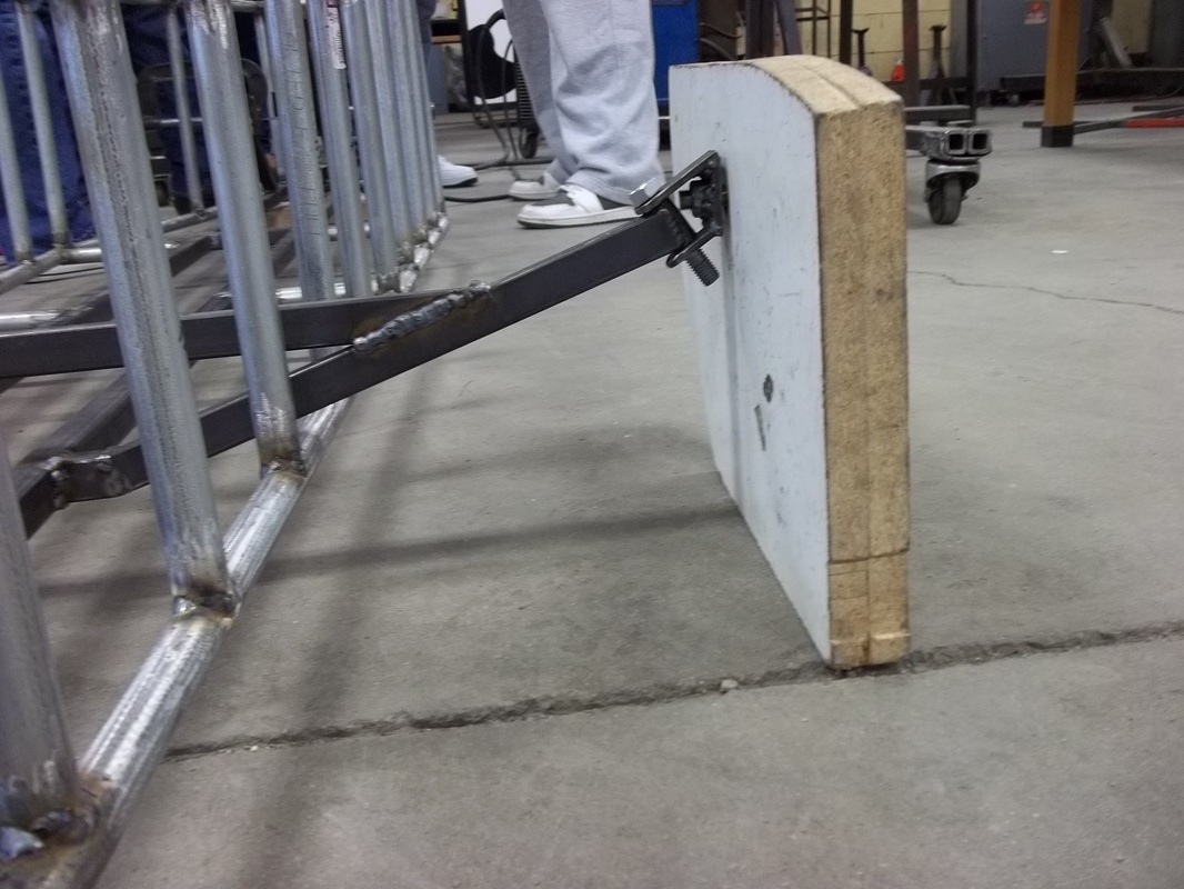
Seat/Harness
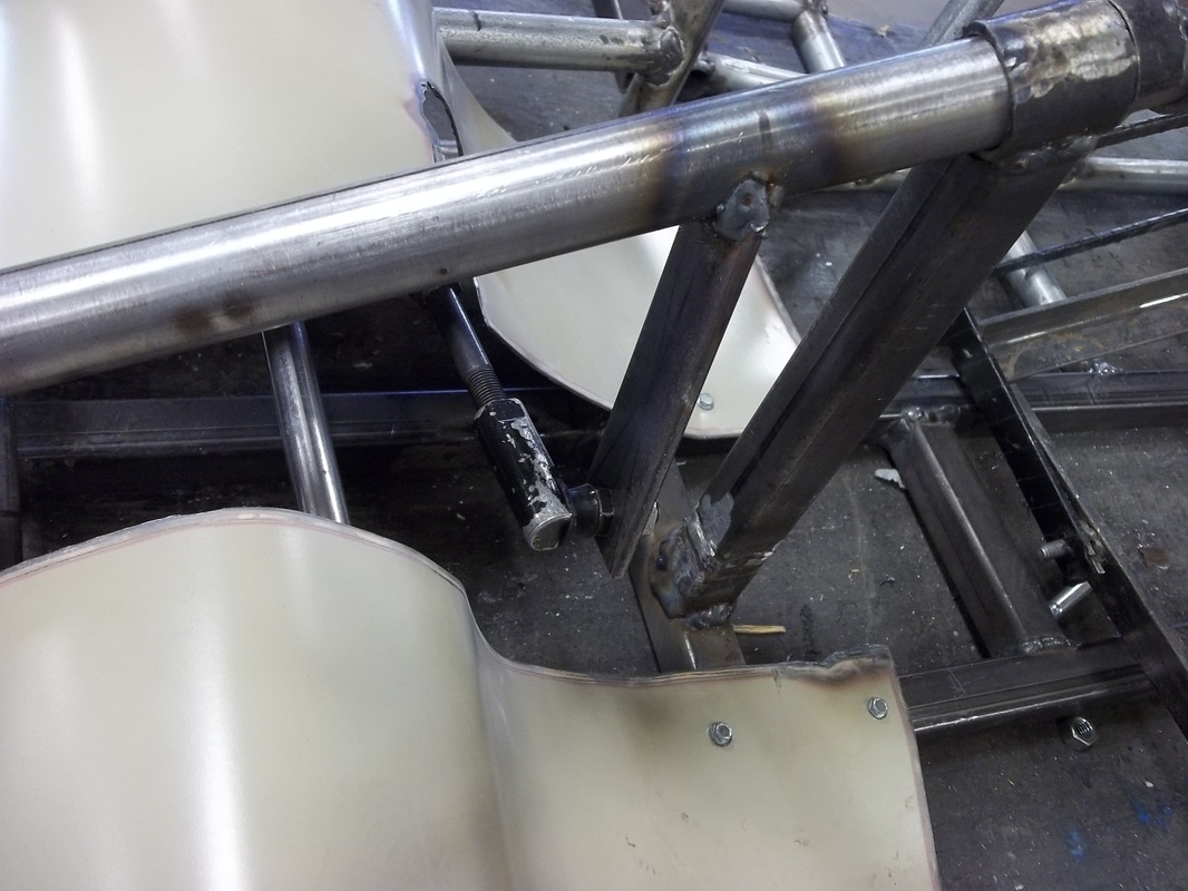
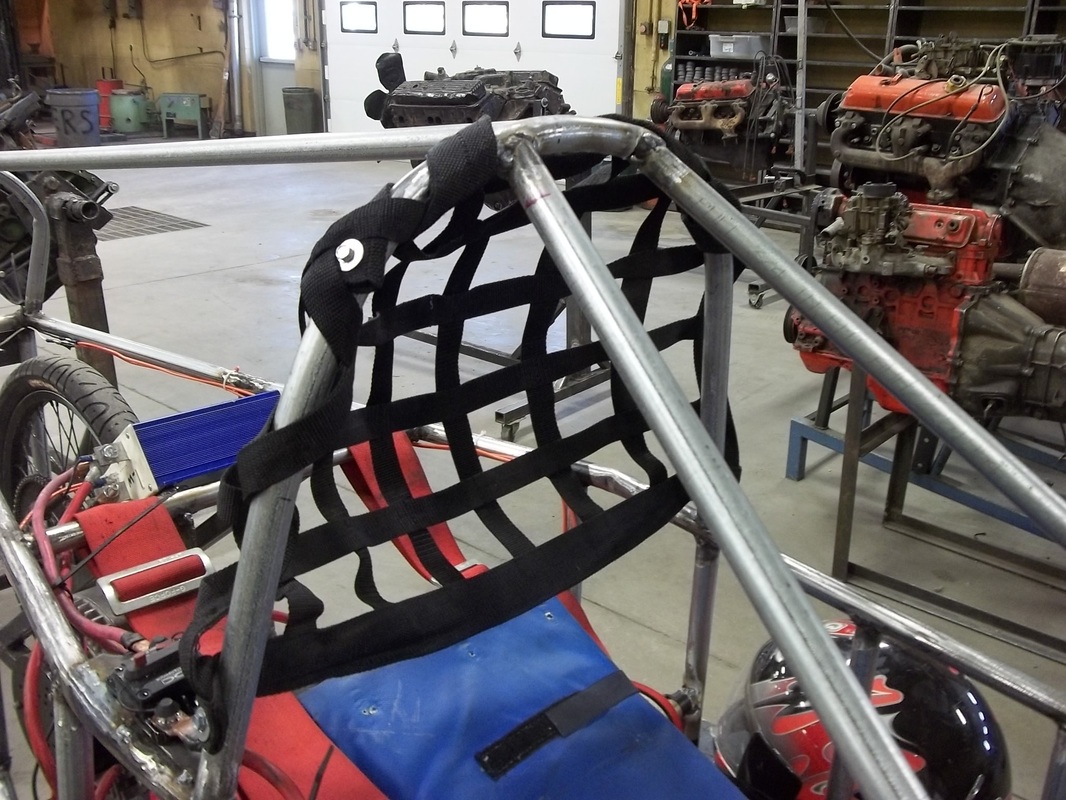
For the head harness we had our driver sit where was it comfortable for him to sit. We simply screwed the head net harness thing to the frame. For our seat we have a wooden board hinged to the frame. We bolted our seat on top of that in the right position. We bolted a secure safety harness to the frame to keep our driver safe and sound.
We started our brake light with a simple brake switch. It has a button on it that when pressed, the brake light goes off. When the button is not pressed our brake light will be on. We made a bracket for our brake switch roughly in the shape of an "L" out of steel plates. We cut a hole in the bracket for our switch to sit in. We welded the bracket to the frame right next to the brake pedal. This way when the brake pedal is pushed forward, the button on the switch will not be pushed and the brake light will light up.
The wires coming out of the switch go straight to the battery and from the battery back to the light.
The light is mounted on the very top, rear part of our frame.
Wiring
Once we figured out how to put our batteries in the battery box, we started with all the wiring. We strung a wire from one battery to the safety switch, then from that switch to the starter switch. From the starter switch we strung a wire to the control box and from the control box back to the other battery. We then put a small wire connecting the two batteries to complete the circuit. We also had to connect the motor to the batteries as well.
Seat/Harness
For the head harness we had our driver sit where was it comfortable for him to sit. We simply screwed the head net harness thing to the frame. For our seat we have a wooden board hinged to the frame. We bolted our seat on top of that in the right position. We bolted a secure safety harness to the frame to keep our driver safe and sound.
First Race
For the first race of the season we strapped up our cars and hit the road down to Lincoln. We raced at the Powerdrive track on East Campus. After we spent half an hour "reorganizing" the tool box, we got to work. At first, we thought we would have problems with getting our driver out of the car in 20 seconds during inspection but we passed with time to spare. The problem was our brakes. For some reason our brakes weren't tightening down enough on the rotor. After tightening them down and taking them off multiple times, we passed inspection and made it on the track at the last second. We beat the other car from our school with a score of 44 laps to their 33.
JANUARY PICTURES
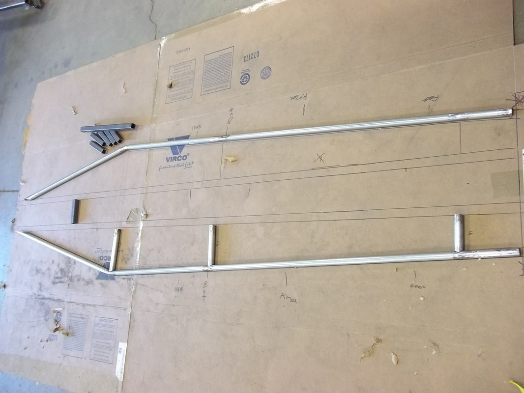
We used a piece of cardboard to draw the outline of our frame on. This is the frame partially assembled.
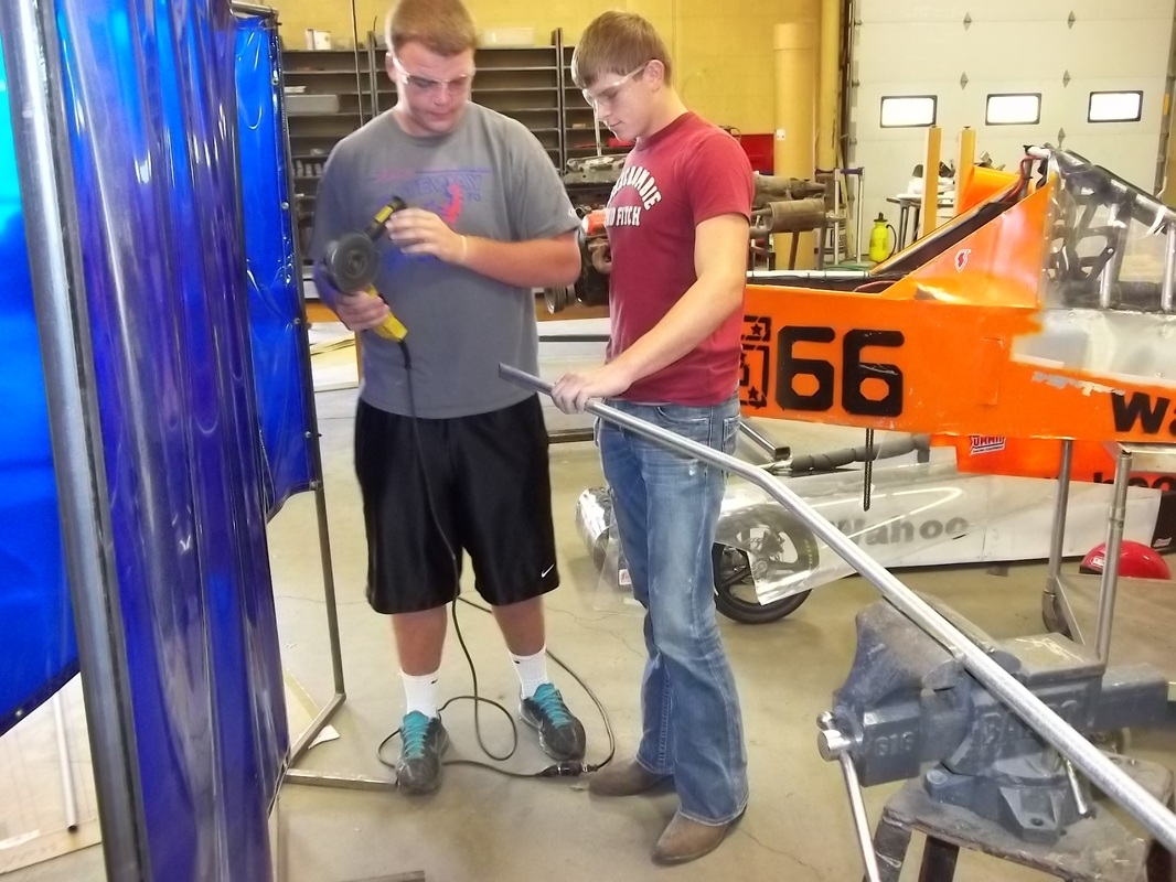
Jason Semrad and Colton Spangler getting ready to grind down a piece of the frame so it fits.
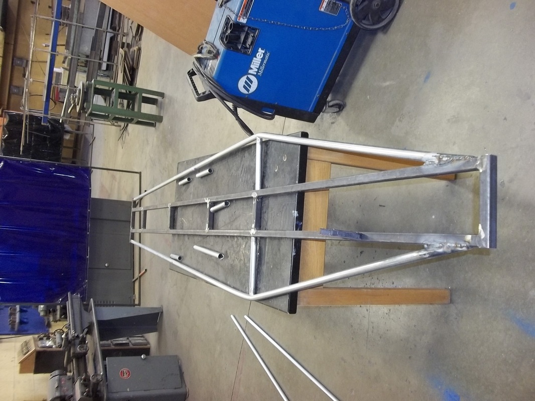
This is the bottom piece of our frame. We used 1X1 square tubing to make the "backbone" of the frame.
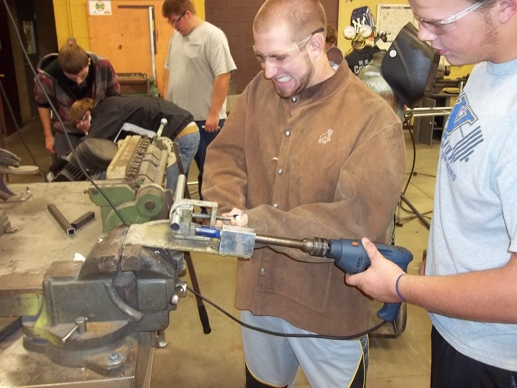
Jason Semrad and Jacob Moline notching a piece of the frame.
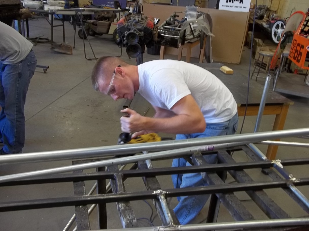
Preston Raymond grinding the frame so we can weld on it.
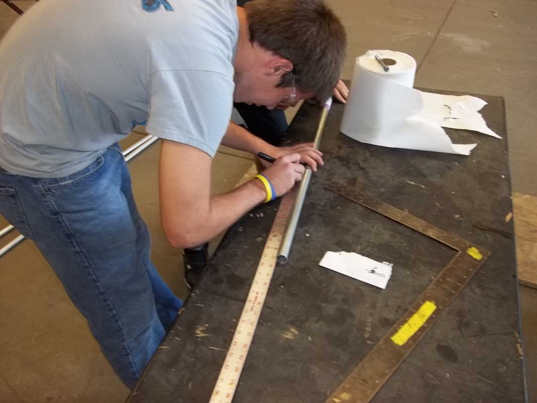
Team Captain Alex Talbott, using his superior brain power to measure a piece of tubing for the frame.
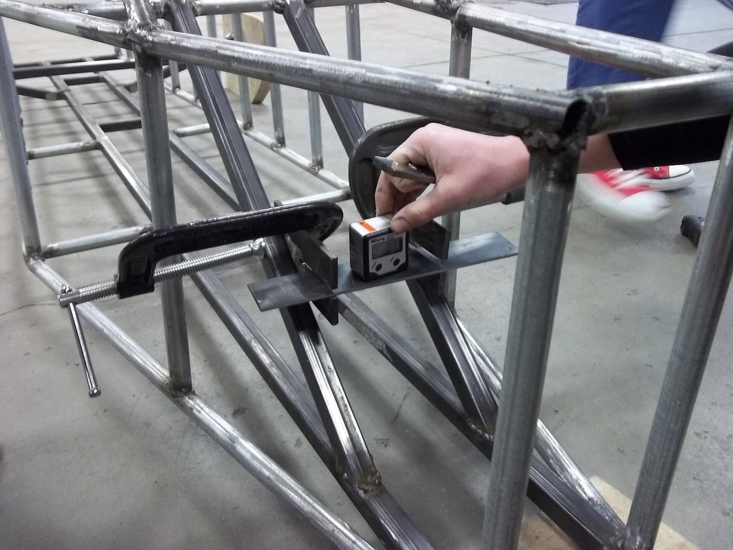
We used a wixey gauge to make sure our back tire mounts were level.
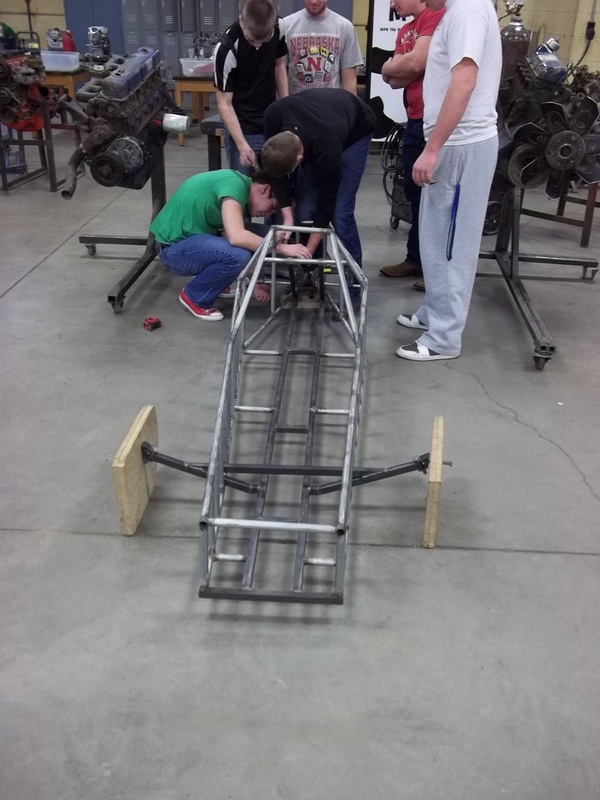
The team working together on lining up our rear tire mount.
Close-up of C-piece and kingpin assembled on front end.
Our C-piece and kingpin assembled with our fake wheels.
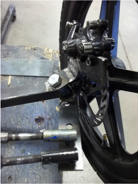
A picture of our assembled brake system. This also shows our two steering rods as they connect to the wheel.
FEBRUARY PICTURES
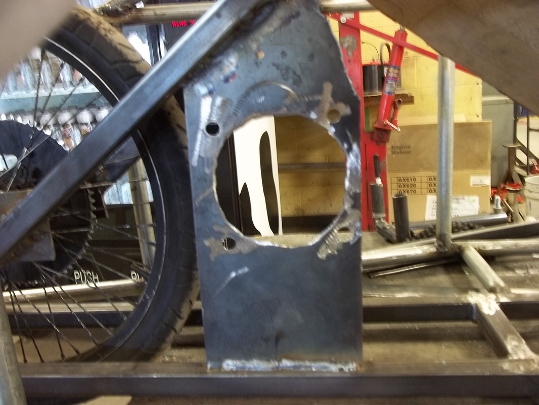
Motor mount
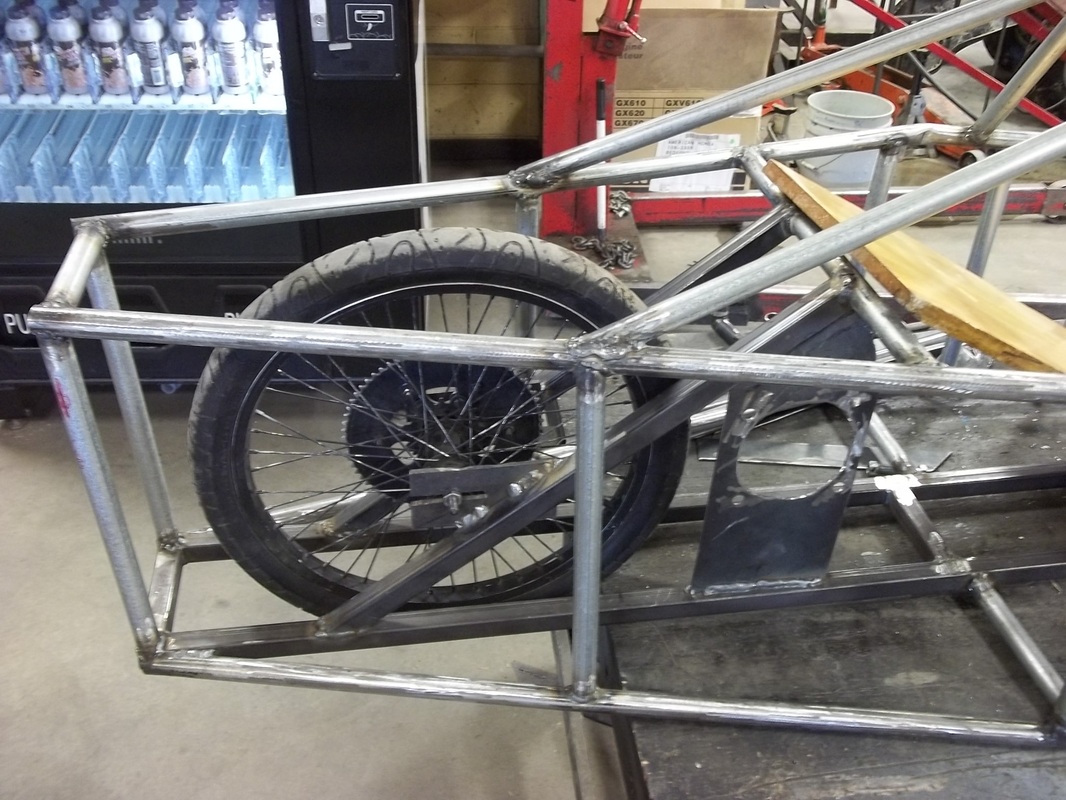
Rear tire and motor mount. And the milk machine.
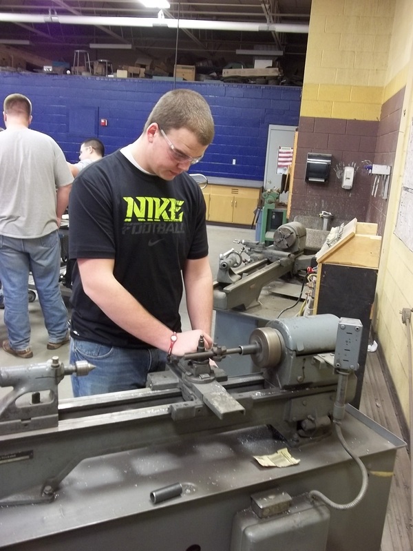
Team member Jason Semrad using the lathe to smooth down the steering column.
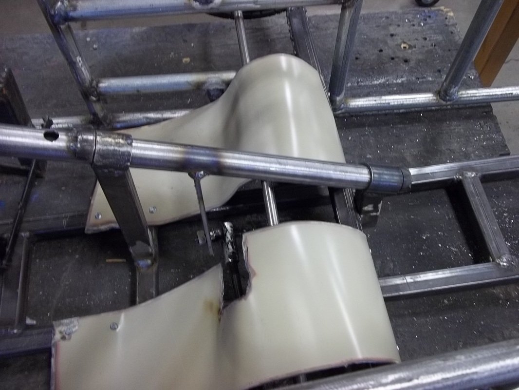
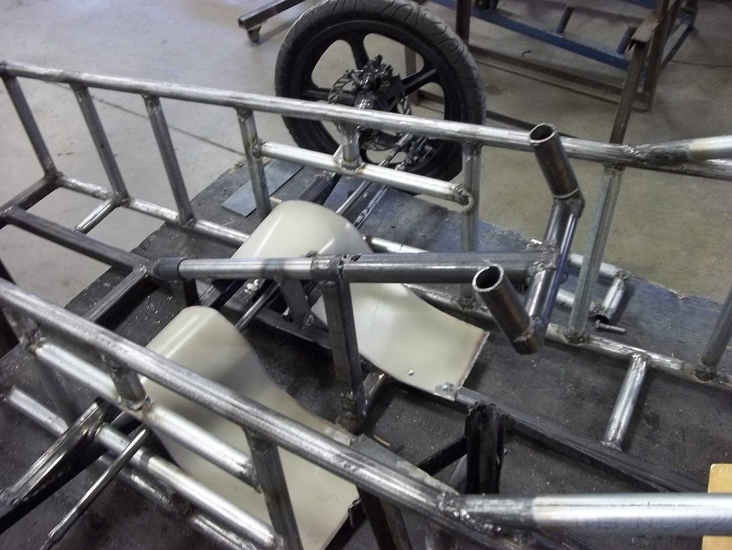
This is the bottom section of our steering column along with our leg covers. This shows our two supports for our column.
Our assembled steering column and wheel.
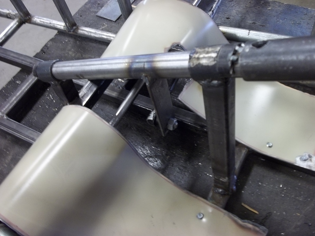
This shows our rectangular piece under the steering column that the arm connects to.
A close up of our steering arm and the piece it connects to.
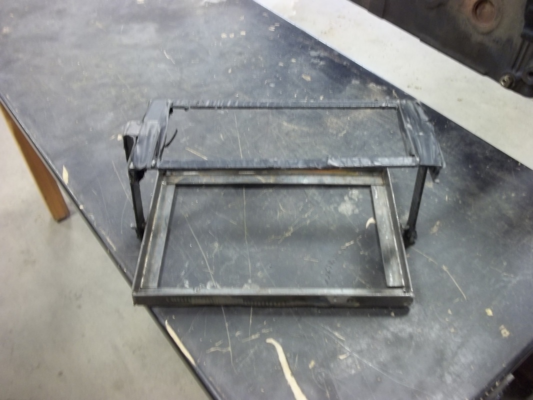
Battery box
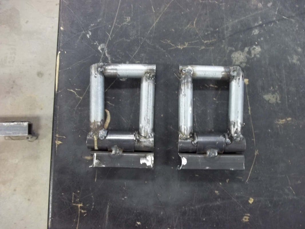
The accelerator and brake pedals
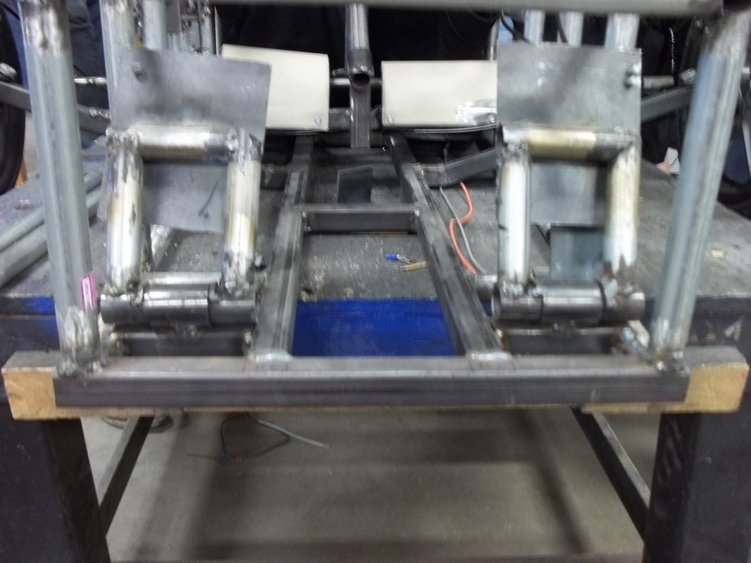
Brake and accelerator pedals welded to the frame.
MARCH PICTURES
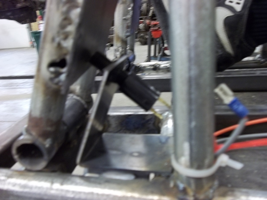
Brake switch bracket with the brake switch welded to the frame.
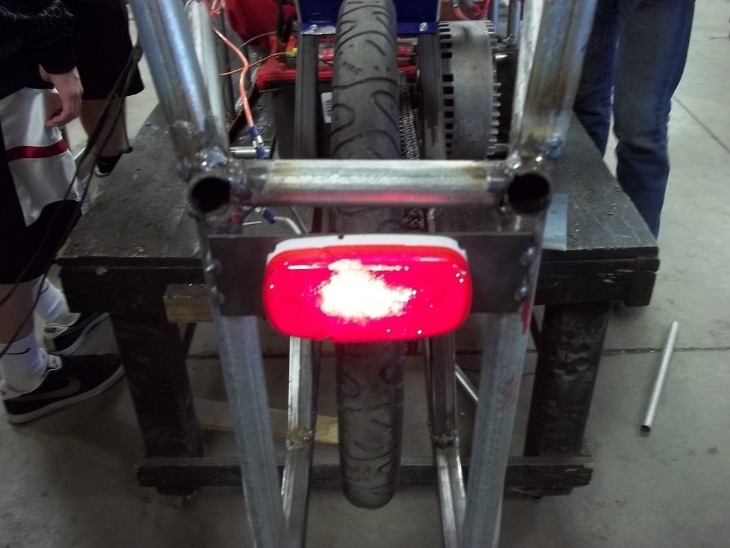
The brake light, lit up like a Christmas tree.
Throttle switch
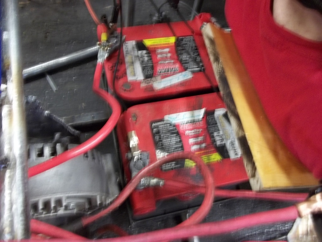
Our two batteries with all the appropriate wiring.
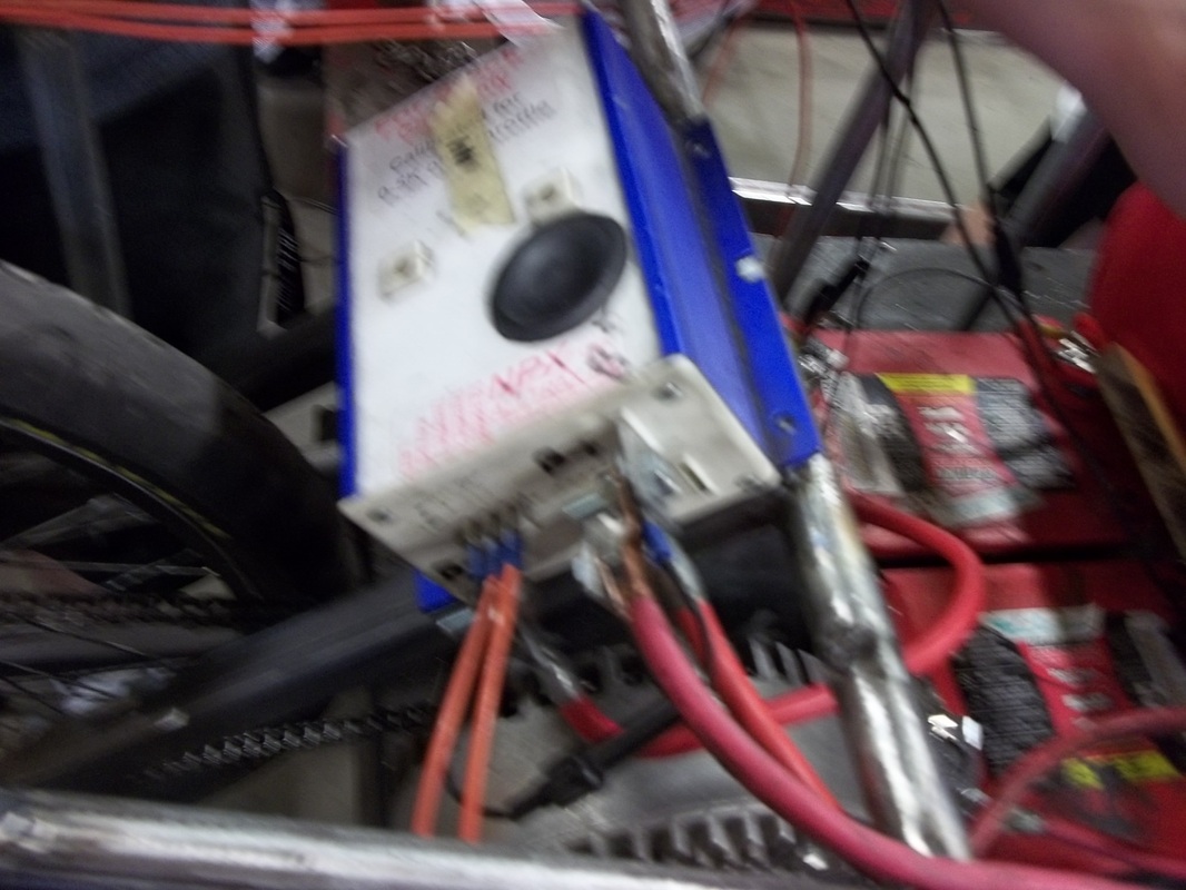
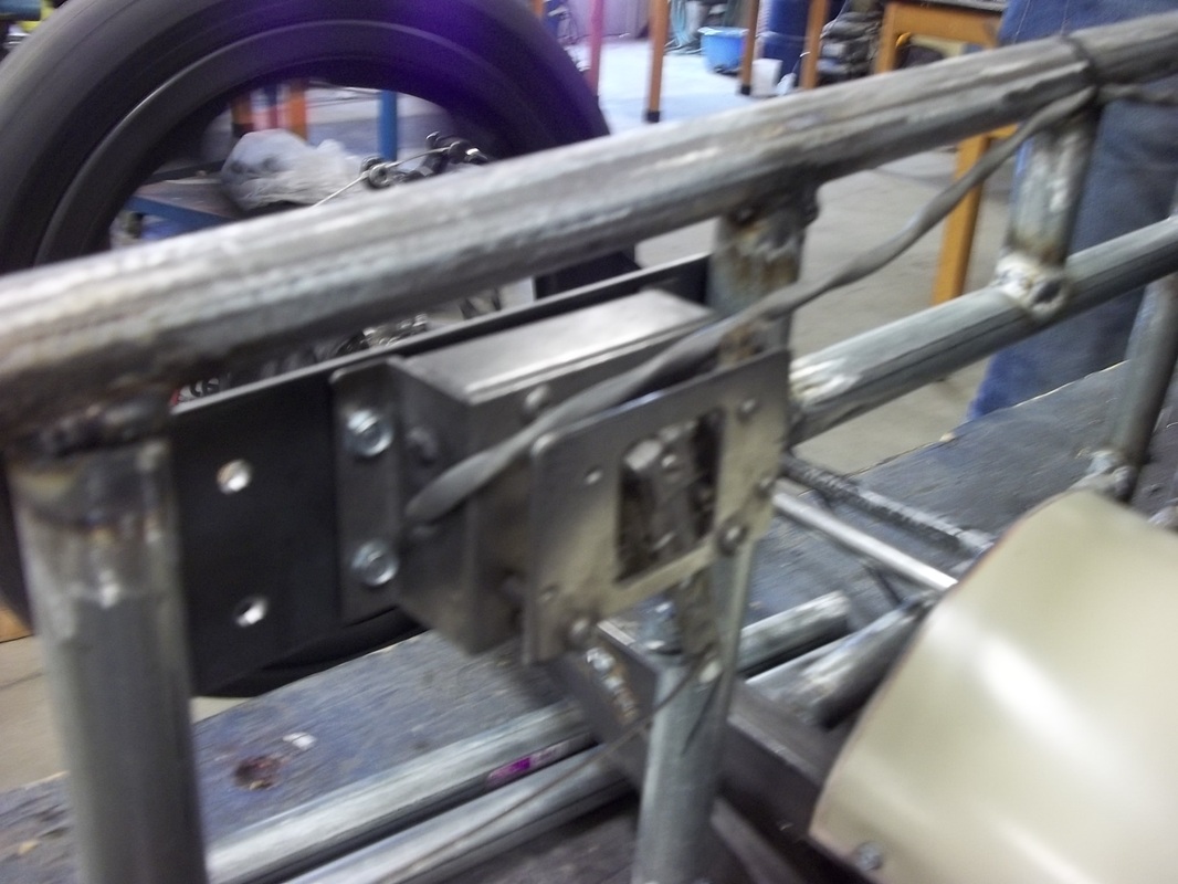
Control box
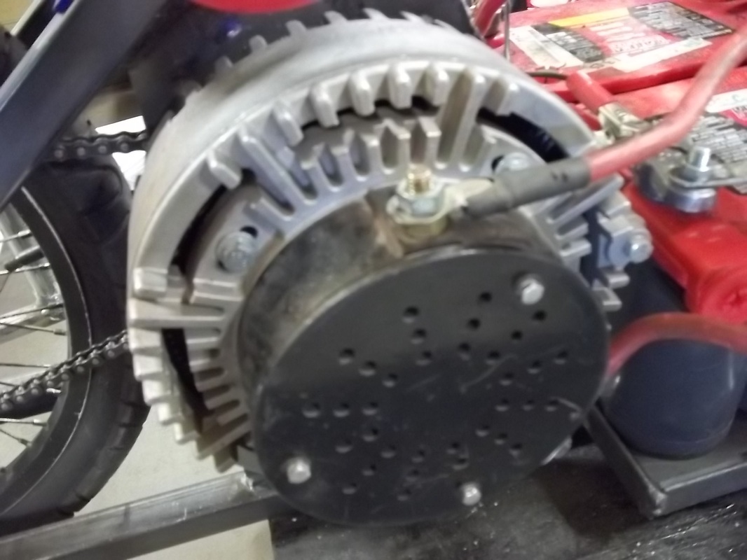
The motor mounted to the motor mount.
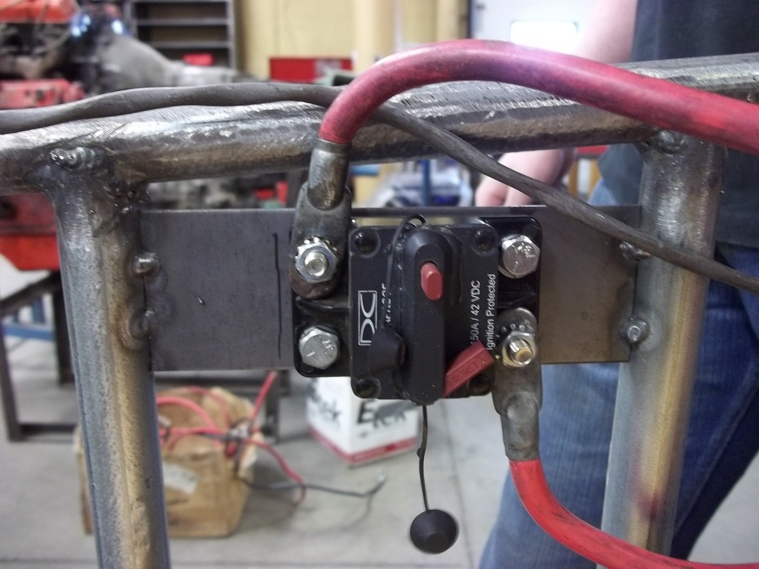
The starter switch.
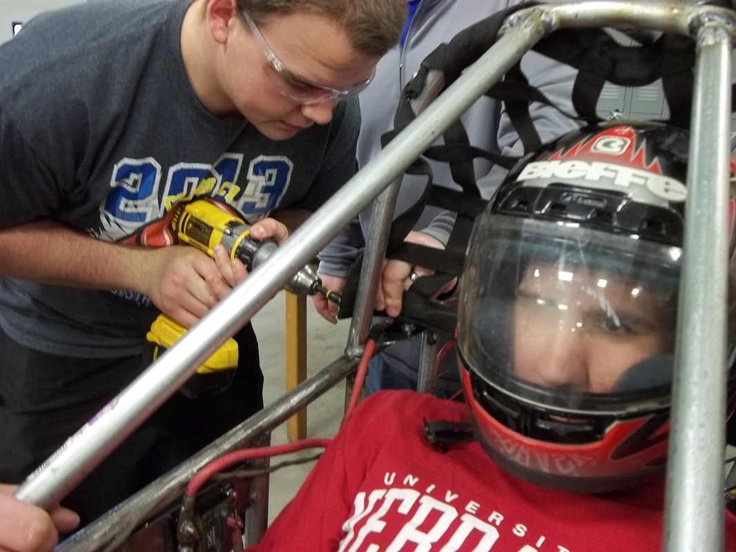
Jason Semrad self-tapping our safety head net thing to the frame.
Our safety harness connected to the frame.
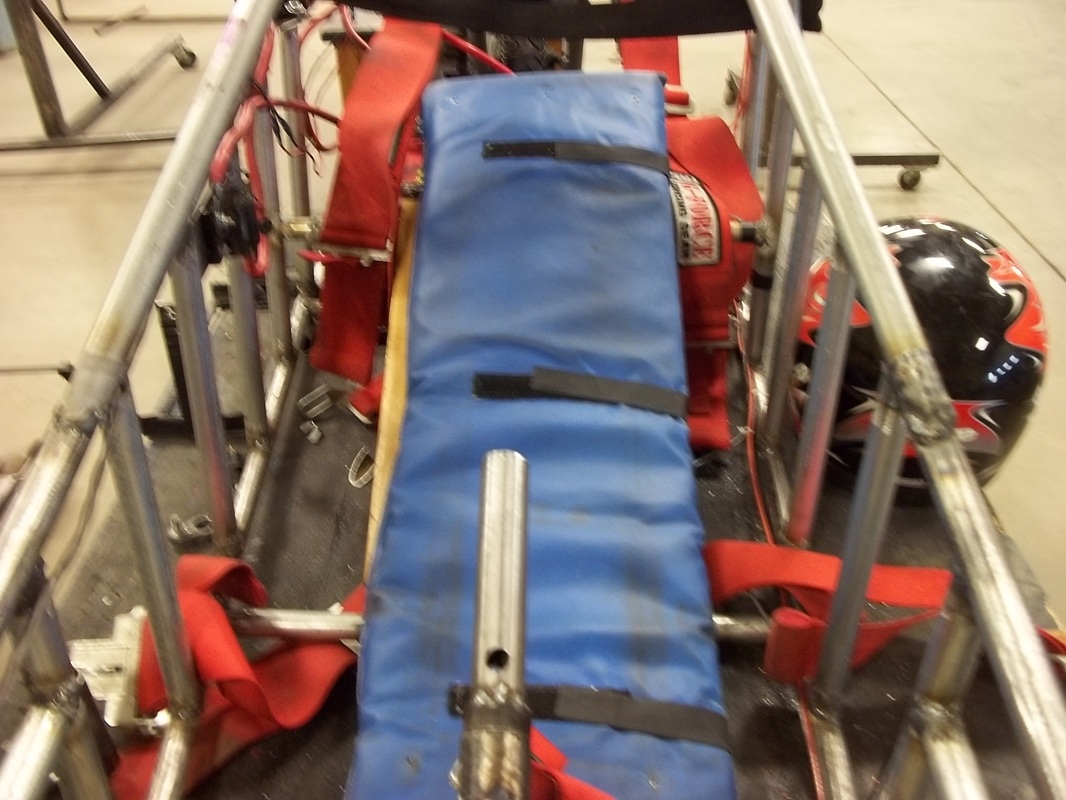
The Throne
